Course: Microwave Engineering | Topic: Waveguides | Target Audience: Electrical Engineering Students
This study guide covers fundamental concepts, mathematical formulations, applications, and comparison of different waveguide types used in microwave engineering.
Waveguide Basics
Waveguides are structures that guide electromagnetic waves from one point to another with minimal loss of energy. They are commonly used at microwave frequencies where conventional transmission lines become inefficient.
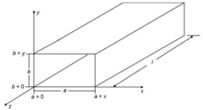
Basic Rectangular Waveguide Structure
Figure: Cross-section of a rectangular waveguide with width 'a' and height 'b'
Why Use Waveguides?
- Low Loss: Waveguides have lower attenuation compared to coaxial cables at microwave frequencies
- High Power Handling: Can handle higher power levels due to their larger physical dimensions
- Shielding: Provide excellent shielding against electromagnetic interference
- Precision: Offer precise control over field configurations and impedance
Key Concept: Cut-off Frequency
Waveguides have a cut-off frequency below which electromagnetic waves cannot propagate. For a rectangular waveguide, the cut-off frequency for the dominant TE10 mode is:
fc = c / (2a)
where 'c' is the speed of light and 'a' is the wider dimension of the waveguide.
Waveguide Types
Different waveguide structures are used depending on the application, frequency range, and power requirements.
| Waveguide Type |
Structure |
Common Uses |
Advantages |
| Rectangular |
Hollow metal tube with rectangular cross-section |
Most common, general microwave applications |
Simple design, easy mode control |
| Circular |
Hollow metal tube with circular cross-section |
Rotary joints, high-power applications |
Symmetrical, no polarization preference |
| Ridged |
Rectangular waveguide with ridges on inner walls |
Wideband applications |
Lower cut-off frequency, wider bandwidth |
| Elliptical |
Flexible waveguide with elliptical cross-section |
Applications requiring flexibility |
Flexible, easier to install in tight spaces |
| Dielectric |
Solid dielectric rod without metal walls |
Optical frequencies, integrated circuits |
No conductor loss, suitable for optics |
Rectangular vs. Circular Waveguides
Rectangular waveguides are preferred when polarization needs to be maintained, while circular waveguides are used when polarization rotation may occur or when symmetrical properties are needed.
The dominant mode in rectangular waveguide is TE10, while in circular waveguide it's TE11.
Propagation Modes
Electromagnetic waves can propagate through waveguides in different field configurations called modes. The two main categories are:
TE Modes (Transverse Electric)
Electric field is entirely transverse to the direction of propagation. No axial component of E-field.
TEmn: Ez = 0, Hz ≠ 0
TM Modes (Transverse Magnetic)
Magnetic field is entirely transverse to the direction of propagation. No axial component of H-field.
TMmn: Hz = 0, Ez ≠ 0
Dominant Mode: TE10
The TE10 mode is the dominant mode in rectangular waveguides because it has the lowest cut-off frequency. Key characteristics:
- One half-wave variation along the width (x-direction)
- No variation along the height (y-direction)
- Electric field is entirely in the y-direction
- Magnetic field has both x and z components
Cut-off Frequency for TEmn Mode
fc(mn) = (c/2π) * √[(mπ/a)² + (nπ/b)²]
Important Note
In practice, waveguides are usually operated in the frequency range between the cut-off frequency of the dominant mode and the cut-off frequency of the next higher mode. This ensures single-mode operation and prevents multimode interference.
Key Waveguide Parameters
Several important parameters characterize waveguide performance:
1. Cut-off Wavelength (λc)
The maximum wavelength (or minimum frequency) that can propagate through the waveguide for a particular mode.
For rectangular waveguide (TEmn mode): λc = 2/√[(m/a)² + (n/b)²]
2. Guide Wavelength (λg)
The wavelength of the electromagnetic wave inside the waveguide, which is longer than the free-space wavelength.
λg = λ0 / √[1 - (λ0/λc)²]
3. Phase Velocity (vp)
The velocity at which the phase of the wave propagates through the waveguide. It is always greater than the speed of light.
vp = c / √[1 - (fc/f)²]
4. Group Velocity (vg)
The velocity at which energy or information propagates through the waveguide. It is always less than the speed of light.
vg = c * √[1 - (fc/f)²]
5. Wave Impedance
The ratio of transverse electric field to transverse magnetic field for a particular mode.
For TE modes: ZTE = η / √[1 - (fc/f)²]
For TM modes: ZTM = η * √[1 - (fc/f)²]
where η = √(μ/ε) is the intrinsic impedance of the medium
Waveguide Applications
Waveguides are essential components in many microwave and RF systems:
Communication Systems
- Satellite Communication: Waveguides connect antennas to transceivers in ground stations
- Radar Systems: Used in both military and civilian radar for high-power transmission
- Cellular Networks: Base stations often use waveguide feeds for antennas
Scientific and Medical Applications
- Particle Accelerators: Waveguides are used to transfer RF power to accelerate particles
- Plasma Heating: In fusion research, waveguides deliver microwave power to heat plasma
- Medical Imaging: MRI machines use waveguides for RF transmission
Industrial Applications
- Microwave Heating: Industrial microwave ovens for drying, curing, and food processing
- Plasma Generation: For semiconductor manufacturing and material processing
- RF Testing: Waveguides are used in test fixtures for device characterization
Further Reading
Textbooks:
- Pozar, D. M. - Microwave Engineering
- Collin, R. E. - Foundations for Microwave Engineering
- Ramo, Whinnery & Van Duzer - Fields and Waves in Communication Electronics
Design Tools
Software for waveguide design and analysis:
- ANSYS HFSS
- CST Microwave Studio
- Keysight ADS
- Online waveguide calculators
Self-Assessment Quiz
Test your understanding of waveguide concepts with these questions:
1. What is the dominant mode in a standard rectangular waveguide?
a) TE11
b) TE10
c) TM10
d) TEM
2. Which of the following is NOT a characteristic of waveguides compared to coaxial cables?
a) Lower loss at microwave frequencies
b) Higher power handling capability
c) Can propagate DC signals
d) Better shielding
3. The cut-off frequency for the TE10 mode in a rectangular waveguide depends primarily on:
a) The height (b) of the waveguide
b) The length of the waveguide
c) Both width and height equally
d) The width (a) of the waveguide
4. Which type of waveguide is most suitable for applications requiring flexibility?
a) Elliptical waveguide
b) Rectangular waveguide
c) Circular waveguide
d) Ridged waveguide
5. In a rectangular waveguide operating in TE10 mode, the electric field is:
a) Parallel to the direction of propagation
b) Perpendicular to the wider dimension
c) Circularly polarized
d) Non-existent
Check Your Answers
Click on any option to see if it's correct. The correct answers will be highlighted in green.