THEORETICAL FOUNDATIONS
Device Structure
1
Electron Gun
Thermionic cathode emitting electrons, accelerated by high voltage (typically 300V-10kV)
2
Buncher Cavity
Input cavity where RF signal velocity-modulates the electron beam
3
Drift Space
Field-free region where bunching occurs due to velocity differences
4
Catcher Cavity
Output cavity where bunched electrons induce amplified RF signal
5
Collector
Absorbs spent electron beam and dissipates heat
Key Equations
DC Electron Velocity
v₀ = √(2eV₀/m) = 0.593×10⁶ √V₀ [m/s]
Where V₀ is beam voltage, e is electron charge, m is electron mass
Velocity Modulation
v(t) = v₀[1 + (β₁V₁/2V₀)sin(ωt)]
β₁ = beam coupling coefficient, V₁ = RF input voltage
Bunching Parameter
X = (β₁V₁/2V₀)(ωL/v₀)
L = drift space length, ω = angular frequency
Output Current (Approximation)
I₂ = 2I₀J₁(X)
J₁(X) = Bessel function of first kind, order 1
Two-Cavity Klystron Schematic
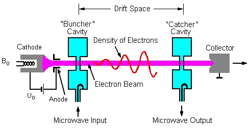
Source: ElProCus