INTRODUCTION TO KLYSTRONS STUDY GUIDE
EEEN 566 - Microwave Engineering
Introduction to Klystrons
A Klystron is a specialized linear-beam vacuum tube used to amplify or generate microwave signals in the range of hundreds of MHz to tens of GHz. Invented by the Varian brothers (Russell and Sigurd) at Stanford University in 1937, the klystron was the first practical device capable of generating significant power at microwave frequencies.
Historical Significance
- 1937: Invented by Russell and Sigurd Varian at Stanford University
- World War II: Critical development for radar technology
- 1948: First high-power klystron developed for linear accelerators
- Modern Era: Essential for satellite communication, radar, and particle accelerators
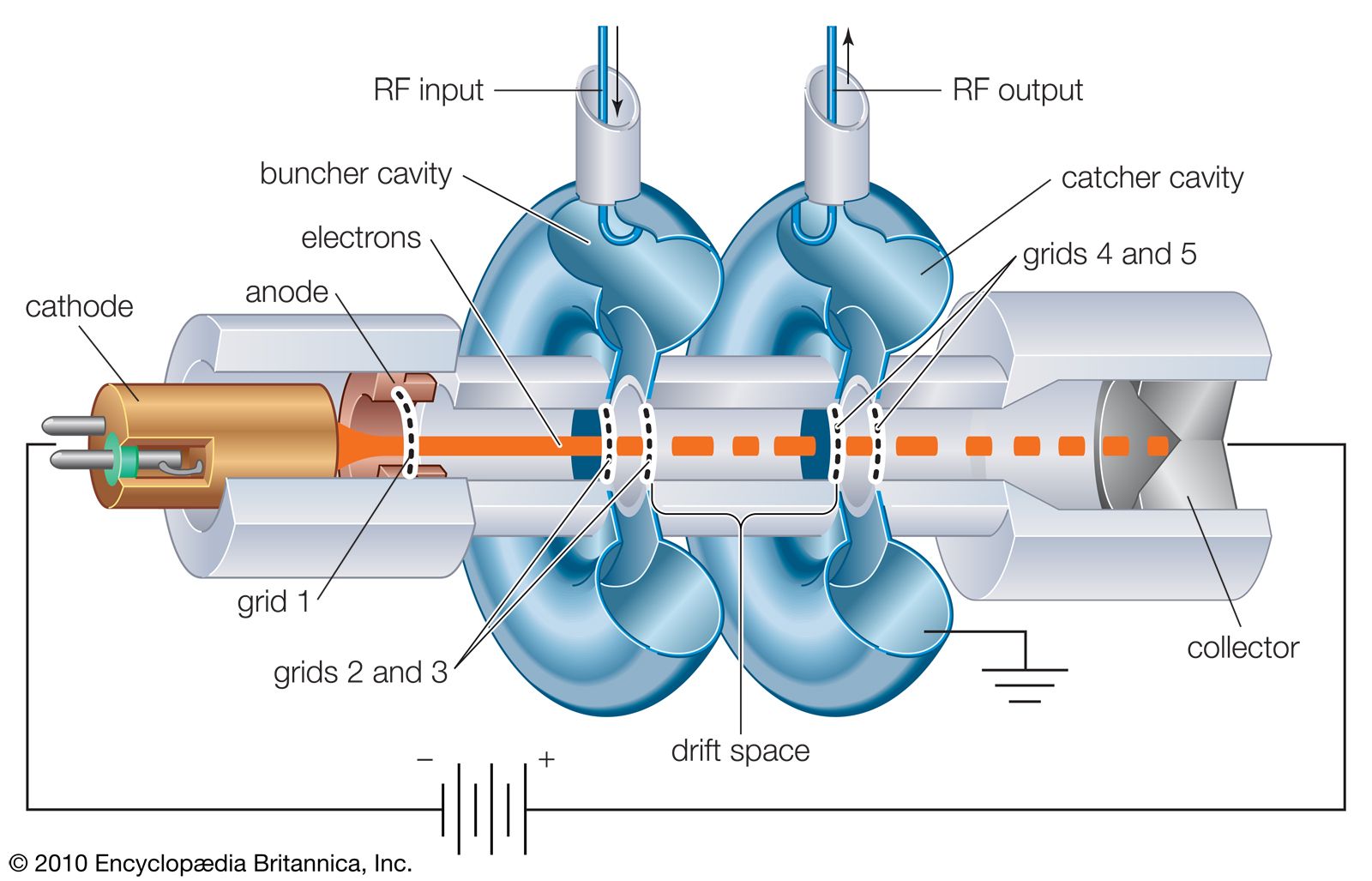
Figure 1: Basic structure of a two-cavity klystron amplifier showing electron gun, buncher cavity, catcher cavity, and collector
Fundamental Operating Principle
The klystron operates on two fundamental physical principles:
- Velocity Modulation: The velocity of electrons in the beam is varied by an RF electric field
- Density Modulation (Bunching): Velocity-modulated electrons form bunches due to differences in transit time
- High power output (up to several megawatts)
- High efficiency (20-60% depending on type)
- Low noise figure
- Excellent frequency stability
- Long operational lifetime
- Requires high voltage power supply (several kV)
- Heavy and bulky due to magnets and cooling systems
- Limited bandwidth (typically 1-2%)
- Expensive manufacturing
Theory of Operation
1. Velocity Modulation
When an electron beam passes through the buncher cavity (input cavity), it encounters an alternating electric field created by the input RF signal. This field accelerates or decelerates electrons depending on the phase of the RF cycle:
- Accelerating Phase: Electrons gain velocity (increase in kinetic energy)
- Decelerating Phase: Electrons lose velocity (decrease in kinetic energy)
- Zero Crossing: Electrons pass through unaffected
Where:
v₀ = DC electron velocity
V₁ = RF voltage amplitude
V₀ = DC beam voltage
ω = angular frequency
2. The Bunching Process
After velocity modulation, electrons enter the drift space (field-free region). Fast electrons catch up with slower ones ahead, while slow electrons fall back toward faster ones behind. This creates electron bunches.
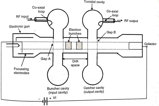
Figure 2: Electron bunching process showing velocity modulation at the buncher gap and density modulation in the drift space
3. Energy Extraction
The bunched electron beam enters the catcher cavity (output cavity) where the bunches induce an RF current. The catcher cavity is tuned to resonate at the signal frequency, and the induced current drives the output load.
Where:
I₀ = DC beam current
R_sh = Shunt impedance of catcher cavity
J₁(X) = Bessel function of first kind (bunching parameter)
X = Bunching parameter = (πN V₁)/V₀
4. Bunching Parameter (X)
The bunching parameter determines the degree of bunching:
Where N is the number of cycles in the drift space transit time.
5. Electronic Efficiency
The theoretical maximum electronic efficiency of a two-cavity klystron is:
For optimal bunching (X = 1.84), the maximum theoretical efficiency is approximately 58%.
Types of Klystrons
1. Two-Cavity Klystron Amplifier
The simplest form consisting of an electron gun, buncher cavity, drift space, catcher cavity, and collector. Used primarily as a power amplifier.
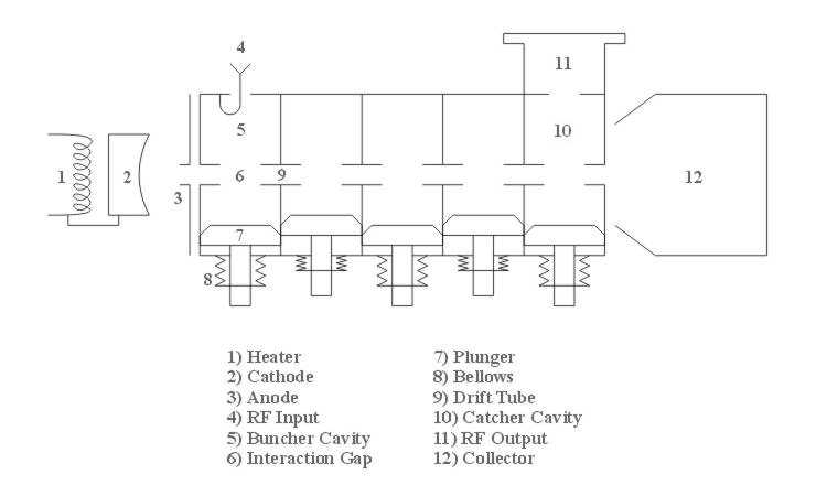
Figure 3: Detailed layout of a two-cavity klystron showing heater, cathode, anode, RF input, buncher cavity, drift tube, catcher cavity, and collector
2. Reflex Klystron Oscillator
Uses a single cavity that serves as both buncher and catcher. A repeller electrode (at negative potential) reflects electrons back through the cavity, creating oscillations.
Where n = 0, 1, 2, ... (mode number)
3. Multi-Cavity Klystron
Contains three or more cavities (typically 3-7) to achieve higher gain (40-60 dB) and bandwidth. Intermediate cavities enhance bunching before the catcher cavity.
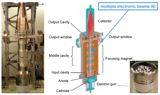
Figure 4: Multi-cavity klystron with input cavity, multiple intermediate cavities, and output cavity for high gain amplification
| Parameter | Two-Cavity | Reflex Klystron | Multi-Cavity |
|---|---|---|---|
| Function | Amplifier | Oscillator | High-gain Amplifier |
| Power Output | 1 kW - 50 kW | 10 mW - 500 mW | 100 kW - 10 MW |
| Efficiency | 20-40% | 10-20% | 30-60% |
| Gain | 10-20 dB | N/A | 40-60 dB |
| Bandwidth | 1-2% | 0.1-1% | 2-10% |
| Applications | UHF TV, Radar | Local Oscillator, Test Equipment | Particle Accelerators, Radar |
Key Components
1. Electron Gun
Produces a high-velocity electron beam through thermionic emission. Consists of:
- Cathode: Heated emitter (typically oxide-coated or thoriated tungsten)
- Grid/Anode: Controls beam current and focuses electrons
- Focus Electrode: Shapes the electron beam
2. Resonant Cavities
Toroidal or cylindrical cavities that act as parallel LC resonant circuits at microwave frequencies. The gap spacing is critical:
Where d = gap spacing, v₀ = electron velocity
3. Drift Space
The field-free region between cavities where velocity modulation converts to density modulation. Length is optimized for maximum bunching:
Where T_b is the bunching period
4. Collector
Captures the spent electron beam. May be depressed (at lower potential) to recover energy and improve efficiency.
5. Focusing System
Maintains beam collimation using:
- Electromagnetic Coils: Solenoid magnets creating axial magnetic field
- Permanent Magnets: For smaller tubes
- Periodic Permanent Magnet (PPM): Alternating magnet poles for weight reduction
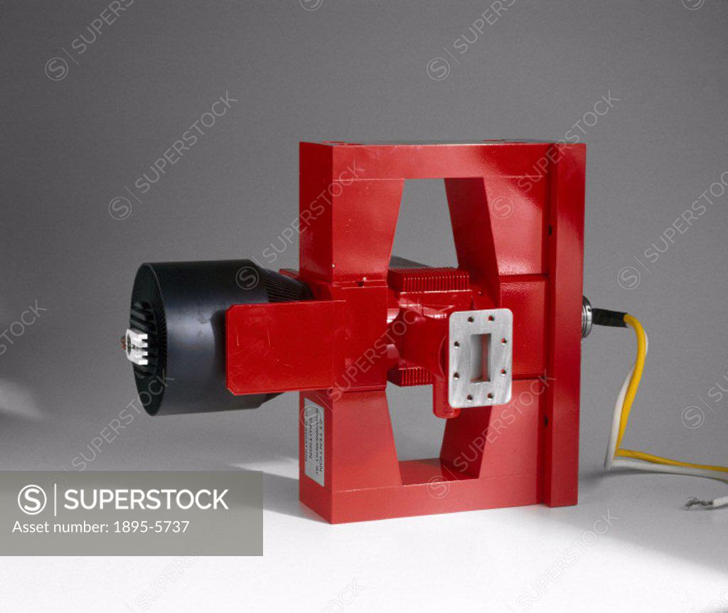
Figure 5: Physical klystron tube showing external magnet structure and waveguide connections
Interactive Klystron Calculator
Electron Velocity Calculator
Relativistic Correction: 0.02%
Bunching Parameter Calculator
Bessel Function J₁(X): 0.582
Theoretical Efficiency: 58.2%
Power Gain Calculator
Output Power: 316 mW
Applications of Klystrons
1. Radar Systems
Klystrons provide the high-power microwave pulses needed for long-range detection in:
- Air traffic control radar (L-band and S-band)
- Weather radar (C-band and X-band)
- Military surveillance and tracking systems
- Airborne intercept radar
2. Particle Accelerators
High-power klystrons (1-100 MW) drive accelerating cavities in:
- Linear accelerators (Linacs) for medical therapy
- High-energy physics research (CERN, SLAC)
- Free-electron lasers
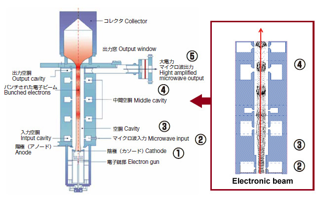
Figure 6: High-power klystron for particle accelerator applications showing multiple beam design
3. Satellite Communication
Used in ground station transmitters for:
- Deep space communication (NASA DSN)
- Broadcast satellite uplinks
- Military satellite communication terminals
4. Broadcasting
- UHF television transmitters (470-890 MHz)
- Digital TV broadcasting (DVB-T)
- FM radio broadcasting (as exciters)
5. Scientific and Industrial
- Plasma heating in fusion research (tokamaks)
- Materials processing (microwave sintering)
- Medical equipment (linear accelerators for cancer treatment)
- Electron paramagnetic resonance (EPR) spectrometers
- Extended Interaction Klystrons (EIK) for wider bandwidth
- Multiple-beam klystrons for higher power density
- Depressed collectors for improved efficiency (up to 70%)
- Periodic permanent magnet (PPM) focusing for reduced weight
Practice Problems
Problem 1: Electron Velocity
A klystron operates with a beam voltage of 15 kV. Calculate the velocity of the electrons. Determine if relativistic effects are significant.
Problem 2: Bunching Parameter
A two-cavity klystron has V₀ = 20 kV, V₁ = 800 V, and drift space length of 3 cm. Operating frequency is 4 GHz. Calculate the bunching parameter and determine if the tube is optimally bunched.
Problem 3: Output Power
A klystron amplifier has I₀ = 2 A, V₀ = 25 kV, and operates with X = 1.84. The catcher cavity shunt impedance is 50 kΩ. Calculate the output power and electronic efficiency.
Problem 4: Reflex Klystron Modes
A reflex klystron operates at 10 GHz with V₀ = 600 V. Calculate the repeller voltage for the n = 2 mode (1¾ mode).
- Remember that optimal bunching occurs at X = 1.84 where J₁(X) is maximum
- Electron velocity calculation is fundamental to all klystron problems
- Always check if relativistic corrections are needed (v > 0.1c)
- Understand the difference between velocity modulation (buncher) and density modulation (drift space)